
Once a plate load test for bearing capacity of soil has been done & dusted, the next big thing is to get your head around the report. At first glance, a plate load test report can look like a right old technical mess, full of graphs, figures and specialist jargon that’s enough to put even the most seasoned engineer off. But don’t worry, you don’t need to have a PhD in geotechnical engineering to get to grips with the key takeaways. For professional testing and clear, actionable reports, visit the plate load test to understand the basis of this test.
At the end of the day, the report is quite simple, really: it’s just a way of confirming whether the ground is safe to support the load that’s put on it. For anyone in civil engineering, working on construction projects, crane pads, piling pads or shallow foundations, understanding this document is crucial if you want to keep on top of construction risk and avoid any dodgy design decisions.
This guide will walk you through what engineers are on the lookout for in a plate load test report and how the data is used to get a handle on soil bearing capacity, settlement behaviour and overall ground suitability.
The Load–Settlement Curve: The Foundation of the Report
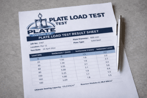
Right at the heart of every plate load test or plate bearing test report is the load-settlement curve. This graph is the result of on-site testing and gives you some pretty reliable data on how the ground behaves under load.
- The vertical axis shows how much load is being applied, or the bearing pressure.
- The horizontal axis shows how much settlement is happening, measured in millimetres.
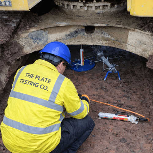
So, here’s how it works: an increasing load is applied to a circular steel plate (usually 300mm or 600mm in diameter, depending on the test). As you add more load in increments, dial gauges are used to measure vertical movement. If the curve is steady and gradual, you’re dealing with competent ground that’s got a good load-bearing capacity. But if there’s a sudden increase in settlement under a relatively small increase in load, that’s when you know you’re dealing with shear failure, and the ground has reached its limit.
This curve is the foundation of all further analysis in the report.
Test Setup and How the Data Is Generated
Understanding the test setup helps explain why the results are considered accurate and reliable.
A typical plate bearing test includes:
- A steel plate (often 300mm or 600mm in plate diameter)
- A hydraulic jack applies a vertical load
- A reaction load, usually provided by construction equipment such as an 8–15 tonne excavator, piling rig, or tracked plant
- A load cell to measure the total load value
- Dial gauges fixed to an independent frame to record settlement
Site preparation usually involves levelling the ground surface and sometimes placing a thin layer of dry sand to ensure full plate contact. The test is performed at the level of the foundation beneath the temporary structure or working platform.
Key Metric 1: Ultimate Bearing Capacity
One of the most important figures in a plate load test for bearing capacity of soil report is the ultimate bearing capacity.
This figure tells you the maximum load that the soil can take before it starts to fail. It’s the point at which settlement increases rapidly with very little increase in load. The value is calculated by dividing the total load that causes failure by the area of the loading plate. It sets the upper strength limit of the ground under the conditions of the test.
This figure isn’t used directly for design, but it’s the foundation for safer calculations.
Key Metric 2: Safe Bearing Capacity
The safe bearing capacity is the ultimate bearing capacity, but with a bit of a safety net. In most cases, a factor of safety is applied, which is usually around 3. So, for example:
- Ultimate bearing capacity: 600 kPa
- Factor of safety: 3
- Safe bearing capacity: 200 kPa
This number tells you the maximum vertical pressure that can be applied without causing too much settlement or failure. Structural engineers use this figure when designing foundations, crane pads, piling pads and working platforms.
Key Metric 3: Settlement Characteristics
The settlement data is recorded at every load increment during the test. What engineers are really interested in is not just how much settlement is happening at failure, but how much settlement is happening under the proposed working load. If there’s too much settlement, you might end up with:
- Cracking foundations
- Uneven floors
- Misaligned construction equipment
- Damage to the foundation beneath temporary structures
By reviewing settlement characteristics under the proposed working load, engineers can get a clear picture of whether the ground will perform acceptably throughout the lifespan of the structure.
Key Metric 4: Modulus of Subgrade Reaction
The subgrade reaction (also known as the Modulus of Subgrade Reaction) tells you how stiff the ground is.
This value is particularly important for:
- Ground-bearing slabs
- Pavements
- Working platforms
- Granular layer design
A higher value suggests stiffer ground that doesn’t need as much structural thickness. A lower value means softer soil that often needs additional reinforcement or a thicker layer to control deformation.
PLT results can also be used to get strain modulus and inform working platform construction designs.
Plate Size and Why It Matters
The plate size used in the test has a direct influence on the results.
- Smaller plates test shallower ground
- Larger plates test deeper soil layers and larger ground particle sizes
Using a larger plate can result in a lower bearing capacity value, as deeper, weaker subgrade layers may influence results. Engineers select plate diameter based on required bearing pressure, desired depth of influence, and available reaction load.
Additional Information Included in the Report
A comprehensive report also documents:
- Test location and depth
- Plate width and diameter
- Maximum particle size observed
- Soil description and moisture condition
- Equipment calibration details
- Test results and total value of applied loads
These details support quality control and help confirm that testing conditions were representative of site conditions.
Plate Load Test vs CBR Test
Now, a CBR (California Bearing Ratio) test tends to be used with fine-grained soil subgrades, where you’re pressing a small point into the ground. But a plate load test looks at a bigger surface area and is better suited for coarse or granular soils.
The good news is that you can use plate load test results to work out an equivalent CBR value, which can be useful if you need to compare the two methods.
Using the Report to Make Informed Decisions
When you’ve got the plate load test services report in front of you:
- Good results mean you can stand by your original design assumptions
- Bad results might mean you need to re-design, maybe even add some ground improvement or choose a different foundation system, which could save you money in the long run and cut down on construction risks.
Final Thoughts
The plate load test for bearing capacity of soil report is a pretty big deal. It gives you reliable data on whether your site is up to supporting construction equipment, temporary structures and permanent foundations. By understanding some basics about how the soil behaves under load, how much pressure it can handle, and how much it settles, engineers and project teams can make some smart decisions that guarantee stability, safety and long-term performance.